加载中...
推荐位 推荐位

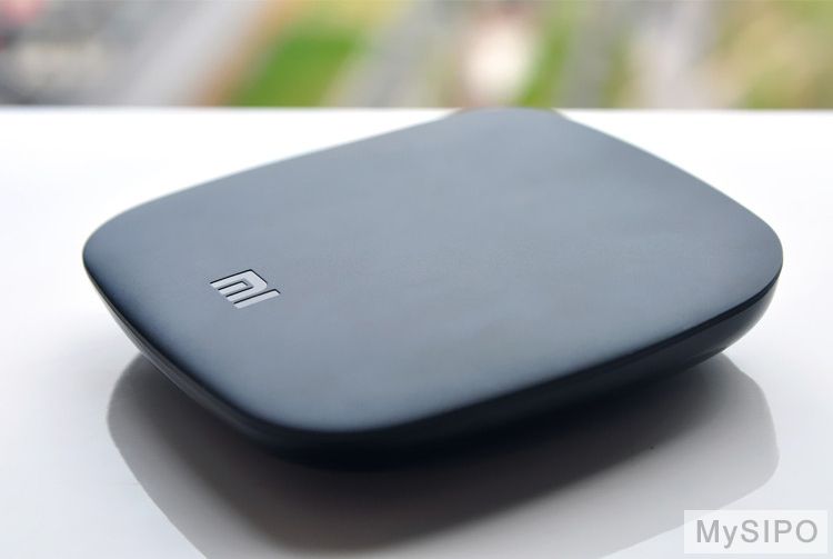
“思博比译活动”摆下翻译擂台,小米盒子等你拿!

发布时间:2015.01.04 北京市查看:8718 评论:43

“思博比译活动”摆下翻译擂台,小米盒子等你拿!


够自信就来参加“思博比译活动”吧。我们将邀请资深老师对答案进行点评,根据点评结果英译中和中译英将各自评出一个优秀奖,奖品为小米盒子哦(没办法,隐古是科技控,喜欢拿电子产品当奖品)
说明:
1、  将下列一段英文的专利文献,翻译成中文或将下列中文文献翻译成英文,二者可以任选其一,也可以都翻译,实力足够强,那就两个奖品都拿走喽。
2、  请将译文在本帖下回复。
3、  活动时间为2015年1月4日至1月31日。在此期限外回复的,将不列为评选对象。

英文文献:Alternatively, sliding joint 326 iscontrolled by a passive mechanical system. In the passive embodiment, slidingjoint 326 is locked and unlocked by a mechanical system. During swing phase,sliding joint 326 is unlocked. As heel strike, the weight of user 90 provides aforce, which pushes down on secondary spring 322. Secondary spring 322 providesshock absorption to allow user 90 to feel a normal step. As main body 304begins to rollover ankle joint 308 to reach the neutral position, slider 330moves with respect to clutch 328 and turns a gear piece within sliding joint326 that locks into place. Once sliding joint 326 is locked, primary spring 320is engaged. As main body 304 continues to rollover ankle joint 308 passed theneutral position, slider 330 pushes down on primary spring 320, compressing andincreasing the potential energy in primary spring 320. Secondary spring 322 isengaged and forced into tension. At toe off, primary spring 320 and secondaryspring 322 want to return to neutral positions. Primary spring 320 extends,pushing foot 306 into toe off. Secondary spring 322 pulls on the heel of foot306 while trying to compress. Both springs work together as joint system 300returns to a neutral position and the toe lifts off the ground, returning energystored in the springs back to the user. Secondary spring 322 neutral positionis in a slightly dorsiflexed position. After toe off, secondary spring 322 actsto move foot 306 to a dorsiflexed position, raising slider 330. As slider 330moves upward with respect to clutch 328, the gear piece within sliding joint326 unlocks, releasing slider 330 and disengaging the primary spring 320.

中文文献:本发明实施例1如下:结合本发明图1至图3可知,一种空气净化器,包括杯体1、端盖2、过滤板3、电机4、扇叶5、吸水器6。所述端盖2安装在杯体1端口,过滤板3通过端盖2压紧于杯体1端口。
所述端盖2内设有一盒体7,电机4及电控元件安装在盒体7内防水,电机的启动开关8设在端盖2表面。端盖2设有进风口9和出风口10,电机4通过电机轴11与扇叶5连接。所述吸水器6形状呈漏斗状,吸水器6顶端设有扣勾12,扣勾12勾挂在扇叶5上与扇叶同步旋转。吸水器6底部设有吸水口13,吸水器6内壁表面沿高度方向设有螺旋槽14。所述杯体1壁上设有透明水尺15,便于观察杯体内水位高度。电机4采用USB插头16。电机驱动扇叶旋转,扇叶带动吸水器旋转,水从吸水口进入吸水器,水沿着吸水器内壁螺旋上升,然后被扇叶打散形成水雾,由于有过滤板的阻挡,水雾大部分位于杯体内腔,与空气进行热交换和湿润空气,由于杯体内压力不断增大,过滤后的湿润空气从出风口进入室内。
本发明实施例2,结合图4可见,实施例2与实施例1区别在于进风口9和出风口10的位置有所不同。


标签: 电子产品 英文文献 思博翻译


分享

收藏(2)

点赞

举报

评论列表

  • 第1楼
    本帖最后由 siceng 于 2015-1-31 22:49 编辑

    2015年1月4日22:05:53
    我先占位,明天再来翻译。认真翻一下。


    2015年1月14日17:57:14
    先做英翻中,如有空再做中翻英。

    可替代地,滑动接头326是由被动机械系统控制的。在该被动实施例中,滑动接头326由机械系统锁定和解锁。在摆动期间,滑动接头326被解锁。当脚后跟击地时,用户90的体重提供向下推压辅弹簧322的力。辅弹簧322提供减震,以允许用户90感觉到正常的步伐。当主要本体304开始翻转踝关节308以到达中间位置时,滑块330相对于离合器328移动,并且在锁定到位的滑动接头326内转动齿轮件。一旦滑动接头326锁定了,主弹簧320就接合了。当主要本体304继续翻转越过中性位置的踝关节308时,滑块330向下推压主弹簧320,压缩主弹簧、并增加在主弹簧中的势能320。辅弹簧322接合了,并且受力张紧。当脚趾离地时,主弹簧320和辅弹簧322想回到中间位置。主弹簧320延伸,推动脚30使得脚趾离地。当尝试压缩时,辅弹簧322拉动脚306的后跟。当接头系统300回到中间位置、并且脚趾抬起离地时,这两个弹簧一起工作,并将存储在这两个弹簧中的能量返回给该用户。辅弹簧322的中间位置是处于稍微翻脚的位置。当脚趾离地之后,辅弹簧322作用,以将脚306移动到翻脚位置,并提起滑块330。当滑块330相对于离合器328向上移动时,在滑动接头326内的齿轮件解锁,释放滑块330,并使得主弹簧320脱离接合。


    2015年1月31日22:37:40
    做了中翻英。


    The embodiment 1 of the present invention is as follows: it can be seen from FIG.s 1 to 3 of the present invention, an air cleaner, comprises a cup body 1, an end cap 2, a filter plate 3, an engine 4, fan blades 5, a water sucker 6. The end cap 2 is mounted at an opening of the cup body 1. The filter plate 3 is tightly pressed on the opening of the cup body 1 via the end cap 2.

    A box body 7 is arranged in the end cap 2. The engine 4 and other electrical control elements are mounted in the box body 7 for water-proof. An start switch 8 of the engine is arranged on a surface of the end cap 2. The end cap 2 is provided with an air inlet 9 and an air outlet 10. The engine 4 is connected with the fan blades 5 via an engine axis 11. The water sucker 6 is funnel-shaped. A hook buckle 12 is provided at the top the water sucker 6. The hook buckle 12 is hooked on the fan blades 5 and synchronously rotates with the fan blades. A water sucker opening 13 is provided at the bottom of the water sucker 6. A spiral groove 14 is provided on a surface of an inner wall of the water sucker 6 along the direction of the height. A transparent water gauge 15 is provided on an wall of the cup body 1 so as to facilitate observing the water level height of the water in the cup body. The engine 4 adopts a USB plug 6. The engine actuates the fan blades to rotate. The fan blades drive the water sucker to rotate. The water is flown into the water sucker through the water sucker opening. The water spirally elevates along an inner wall of the water sucker, and then is broken up by the fan blades so as to form a water mist. Because of the obstruction of the filter plate, most of the water mist is located in an inner cavity of the cup body so as to exchange heat with the air and to humidify the air. Because the pressure in the cup body continuously increases, the filtered humid air is flown into the room from the air outlet.

    The embodiment 2 of the present invention is as follows: it can be seen from FIG. 4, the difference between the embodiment 2 and the embodiment 1 focuses on the different positions of the air inlet 9 and the air outlet 10.

    2015/01/04 22:05 [来自北京市]

    0 举报
  • 第2楼
    英译中:
    或者通过被动式机械系统来控制滑动接头326。在被动式实施例中,滑动接头326是通过机械系统来锁定和解锁。在摆动阶段期间,滑动接头326解锁。在脚后跟踩上时,使用者90的重量提供了在辅助弹簧322上向下推的力。辅助弹簧322提供减震从而让使用者90感觉到正常的踏步。在主体304开始使踝关节308翻转而到达中性位置时,滑块330相对于离合器328移动并使滑动接头326内的锁定到适当位置的齿轮片转动。一旦滑动接头326锁定,主弹簧320便接合。在主体304继续使踝关节308翻转经过中性位置时,滑块330在主弹簧320上向下推动,从而压缩并增加主弹簧320中的势能。辅助弹簧322接合并被强制张紧。在脚趾离地阶段,主弹簧320和辅助弹簧322趋于返回到中性位置。主弹簧320延伸,从而推动足部306使脚趾离地。辅助弹簧322在足部306的脚后跟上拉动,同时尝试进行压缩。在关节系统300返回到中性位置并且脚趾抬起离开地面时主弹簧和辅助弹簧一起工作,从而将储存在弹簧中的能量返回给使用者。辅助弹簧322中性位置是在稍微背屈的位置中。在脚趾离地阶段之后,辅助弹簧322进行作用而将足部306移动到背屈位置,从而升高滑块330。在滑块330相对于离合器328向上移动时,滑动接头326内的齿轮片解锁,从而释放滑块330并使主弹簧320脱离。

    来自群里,qq:10046100,献丑了。

    2015/01/05 09:02 [来自新加坡]

    0 举报
  • 第3楼
    本帖最后由 celiawlh 于 2015-1-6 14:17 编辑

    可替代地,滑动接头326通过主动机械系统被控制。在被动的实施例中,滑动接头326通过机械系统被锁定和解锁。在摇摆阶段期间,滑动接头326被解锁。当踵状物冲击时,用户的重量90提供力矩,其在辅助弹簧322上向下推动。辅助弹簧322提供减震来允许用户90来感觉正常的台阶。当主体304开始在踝部接头308上方滚转来到达中立位置时,滑动件330相对于离合器328运动并且使在锁定就位的滑动接头326内的齿轮件转动。一旦滑动接头326被锁定,主弹簧320被接合。当主体304继续在踝部接头308上方滚转经过中立位置时,滑动件330在主弹簧320上向下推动,压缩并且增加主弹簧320中的势能。辅助弹簧322被接合,并且被促使进入拉紧状态。在脚趾离地时,主弹簧320和辅助弹簧322希望来返回中立位置。主弹簧320延伸推动足部306变得脚趾离地。辅助弹簧322在足部306的踵状物上拉动,同时试图来压缩。当接头系统300返回至中立位置时,两个弹簧一起作用,并且脚趾提起离开地面,使储存在弹簧中的能量回到用户。辅助弹簧322中立位置处于略微向背侧屈曲的位置。在脚趾离地之后,辅助弹簧322作用将足部306移动至向背侧屈曲的位置,使滑动件330升高。当滑动件330相对于离合器328向上移动时,在滑动接头326内的齿轮件解锁,释放滑动件330并且使主弹簧320脱离。

    2015/01/06 14:15 [来自北京市]

    0 举报
  • 第4楼
    可选的,滑动接头326由被动的机械系统控制。在该实施例中,滑动接头326通过机械系统被锁定、解锁。在摆动阶段,滑动接头326解锁。当脚跟冲击,使用者90的重量提供一力,向下作用于副弹簧322。副弹簧322提供减震以使使用者90感觉步伐正常。主体304开始绕踝关节308转动达到中间位置,滑块330相对于离合器328的滑动驱动滑动接头326内的齿轮片从而锁定到位。一旦滑动接头326锁定,主弹簧320接合。当主体304继续绕踝关节308转动越过中间环节,滑块330向下推动主弹簧320,压缩并增加主弹簧320的势能。副弹簧322接合并拉伸。在脚趾移走,主弹簧320和副弹簧322有回到中间位置的趋势。主弹簧320伸长,把脚306到脚趾。副弹簧322的压缩趋势牵引脚306的跟部。在连接系统300回复到中间位置并且脚趾抬离地面的过程中两个弹簧共同作用将存储在弹簧中的能量返回给使用者。副弹簧322中间位置处于一个自然弯曲位置。当脚趾离开后,副弹簧322使脚306移动至自然弯曲的位置并提高滑块330。当滑块330相当于离合器328对向上移动,滑动接头326内的片齿轮解锁,释放滑块330并分离主弹簧320。

    2015/01/06 21:58 [来自北京市]

    0 举报
  • 第5楼
    英翻中报名参加,译文如下

    另一种方案是,滑动关节326由被动机械系统控制。在被动模式下,滑动关节326由机械系统来闭锁及解锁。在转弯阶段,滑动关节326闭锁。由于脚跟著地,用户90的重量提供了一股将辅助弹簧90向下推动的力量。辅助弹簧322能够吸收冲击力,使得用户90感到步伐正常。主体304开始 翻滚,踝关节308达到中位,滑块330向离合328移动,并带动滑动关节326内的齿轮,到闭锁位。一旦滑动关节326闭锁,主弹簧320被占用。主体304继续翻滚,踝关节308越过中位,滑块330将主弹簧320向下推,压迫并增大主弹簧320的势能。辅助弹簧322被占用,并被强迫张拉。在足趾离地时,主弹簧320和辅助弹簧322要回到中位。主弹簧320伸长,推动足部306的足趾离地。辅助弹簧322拉动306的足跟部,试图压缩。两个弹簧同时作为一个系统300协同工作,返回中位,使得足趾离地,将能量储存于弹簧并带回给用户。辅助弹簧322的中位略呈背屈。在足趾离地后,辅助弹簧322开始将足部306推向背屈位置,提升滑块330。由于滑块330向离合328方向上升,滑动关节326内的齿轮解锁,释放滑块330,并解除对主弹簧320的占用。

    2015/01/07 09:28 [来自中国香港]

    0 举报
  • 第6楼
    本帖最后由 liliteng 于 2015-1-7 11:15 编辑

    或者是,滑动接头326是由被动机械系统所控制。在被动式的实施方式中,利用机械系统来锁定及解锁滑动接头326。在摆荡期中,将滑动接头326解锁。当脚跟着地时,用户90的体重提供了一外力,进而将二系弹簧322向下压。二系弹簧能够吸收冲击,而使得用户感受到一般正常的跨步。当本体304开始转动关节接头308使其到达中立位置时,滑件330沿着接合器328移动并转动滑动接头326内的齿轮件而使其锁定于定位。一旦滑动接头326经锁定,一系弹簧320就会被接合。当本体304继续转动关节接头308而使其超过中立位置时,滑件330下压至一系弹簧320上,因而压缩一系弹簧320并增加一系弹簧320中的势能。二系弹簧322会被接合并被迫处于拉张状态。在脚趾离地期,一系弹簧320与二系弹簧322会想要回归到中立位置。一系弹簧320延伸,进而将脚掌306推动到脚趾离地的状态。二系弹簧322在尝试压缩的过程中会将脚掌306的脚跟向下拉。当接头系统300回到中立位置,且脚趾离开地面时,两种弹簧协力合作下,将所储存的能量回传给用户。二系弹簧322的中立位置是处于略微踝背屈的位置。当脚趾离地后,二系弹簧322作动以将脚掌306移动到踝背屈位置,进而抬高滑件330。当滑件330相对于接合器328向上移动时,滑动接头326内的齿轮件解锁,进而松开滑件330并与一系弹簧320脱离。
    The embodiment 1 of the present inventionis as follows.  As illustrated in Figure1 to Figure 3 of the present invention an air cleaning apparatus comprises acup body 1, an end cover 2, a filtering plate 3, an electro-mechanical device 4,a fan blade 5, and an water-absorbing device 6. The end cover 2 is installed on the end opening of the cup body 1, andthe filtering plate 3 is tightly pressed against the end opening of the cupbody 1 through the end cover 2.
    The end cover 2 has a box 7 disposedtherein, and the electro-mechanical device 4 and the electronic-controlledcomponent are disposed in the box 7 for waterproof, while the activation switchof the electro-mechanical device 4 is disposed on the outer surface of the endcover 2.  The end cover 2 has an intakeopening 9 and a discharge opening disposed thereon, and the electro-mechanical device4 is coupled with the fan blade 5 via an electro-mechanical shaft 11.  The water-absorbing device 6 has a funnel shape,and has a fastening hook 12 disposed at the top end thereof.  The fastening hook 12 is hooked on the fanblade 5 so that it rotates synchronously with fan blade.  The water-absorbing device 6 has awater-absorbing inlet 13 disposed at the bottom thereof, and the inner surfaceof the water-absorbing device 6 has a helical groove 14 disposed thereon along theheight direction.  The wall of the cupbody 1 has a transparent gage 15 disposed thereon to facilitate the observationof the water stage within the cup body. The electro-mechanical device 4 employs a universal serial bus (USB)socket.  The electro-mechanical device isconfigured to drive the rotation of the fan blade, which in turn promotes therotation of the water-absorbing device; in this case, water enters the water-absorbingdevice through the water-absorbing inlet, raising along the helical groove onthe inner wall of the water-absorbing device, and then, water i****attered bythe fan blade to form the mist.  Due tothe blockade of the filtering plate, most of the mist resides within the innercavity of the cup body where it exchanges heat with and moisten the air.  As the pressure within the cup body continuesto increase, the filtered, moisten air enters the room through the dischargeopening.
    The embodiment 2 of the present inventionis illustrated in Figure 4.  The distinguishmentbetween the embodiment 2 and embodiment 1 lies in that the positions of the inletopening and the discharge opening are different.

    2015/01/07 10:25 [来自中国台湾]

    0 举报

快速回复